A tendon-driven continuum robot bends like a trunk. Drilled disks sit on a flexible backbone, and pulling the tendons that run through their eyelets curls it. In the usual constant-curvature model the backbone bends into a circular arc, and each tendon must change length by −θ·r·cos α: the tendon on the inside of the bend is pulled in, the one outside is let out. A Panel shows those changes live.
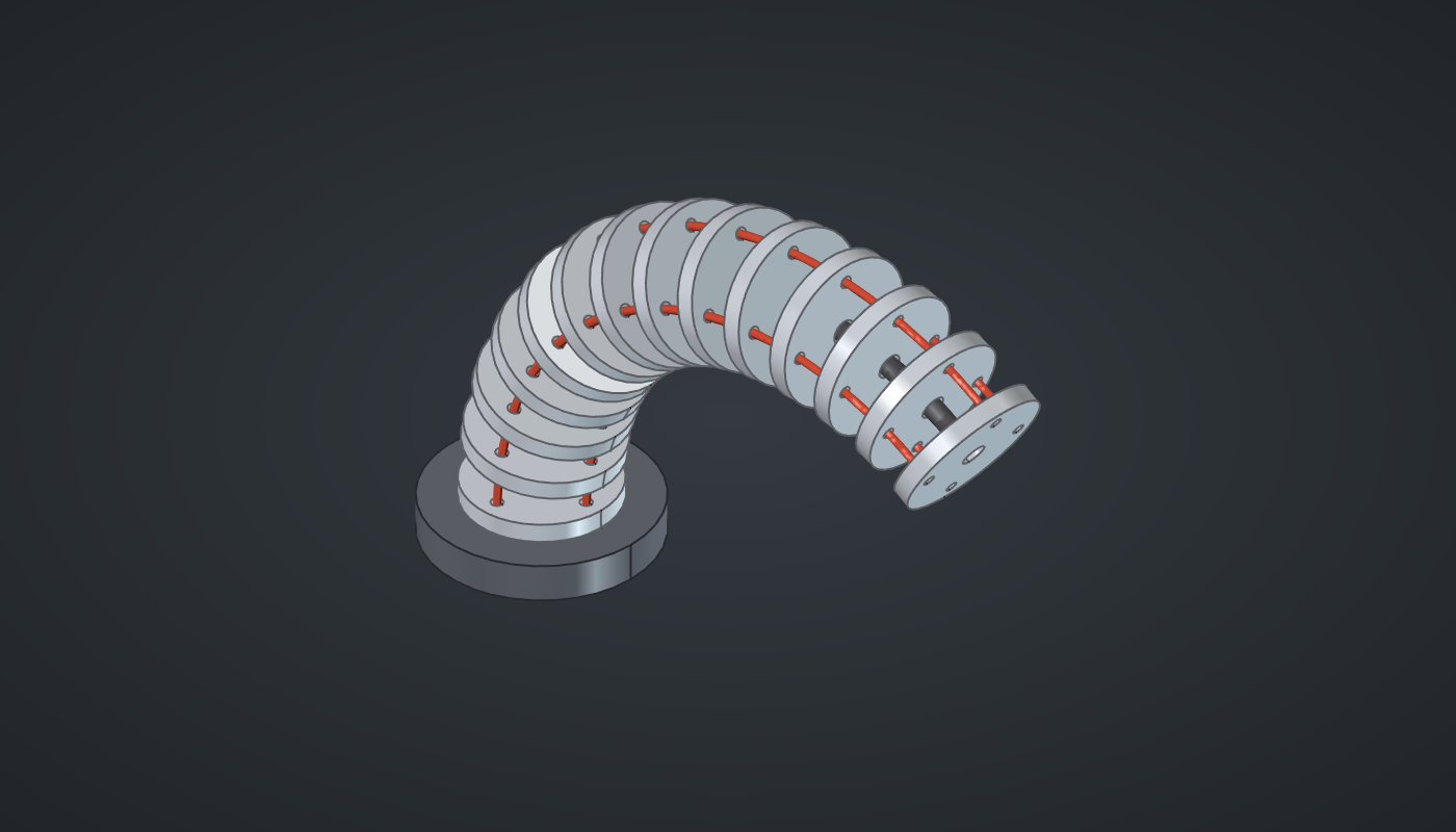
Reference: choose on the canvas toolbar to load the finished definition.
Build it
One vertebra
-
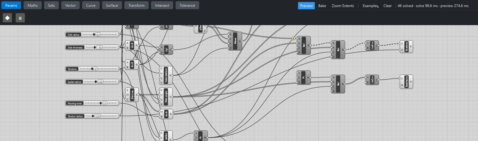
Place nine sliders: Disks: 14 (4 – 30) with Decimals
0, Length: 60 (20 – 120), Bend: 120 (1 – 270), Disk radius: 6 (3 – 12), Disk thickness: 1.5 (0.5 – 4) with Decimals2, Tendons: 4 (2 – 8) with Decimals0, Eyelet radius: 4.5 (1.5 – 10) with Decimals2, Routing twist: 0 (-30 – 30) and Tendon radius: 0.3 (0.1 – 1) with Decimals2. -
Place a Cylinder (Surface) of Disk radius and Disk thickness, moved down by half the thickness (Multiplication ×
-0.5, Move): the disk, centred on z = 0. -
Place a Circle (Curve) of Eyelet radius, a Divide Curve (Curve) with Tendons → N, and a Deconstruct (Vector): the eyelet positions.
-
Place a Cylinder for the holes (radius Tendon radius ×
1.6, length thickness +2), an Expression (Maths),-x/2 - 1, of the thickness, and a Move to the eyelets. Do the same for a central hole of radius1. -
Place a Solid Difference (Intersect), Vertebra, with the disk and both sets of holes wired into B.
The bend
-
Place a Series (Sets), Disk no., with Disks → C, and an Expression, Disk angle,
x*y/(z - 1), with the disk no., Bend and Disks: from 0 to the full bend. -
Place an Expression, Bend radius,
x/radians(y), with Length and Bend, and a Construct Point (Vector) at (radius, 0, 0): the centre of curvature. -
Place a Multiplication of the disk no. by Routing twist, and a Rotate (Transform) of the vertebra by it, about Z: each disk turned a little more round its own axis.
-
Place a Rotate, Vertebrae, with the disk angles → A, the centre → C and X (axis)
0, 1, 0.
Tendons, backbone and pull
-
Place two Rotate components for the eyelet points, the same two turns, with Graft on the first one’s G: one branch per tendon, its eyelet at every disk. Place an Interpolate (Curve) and a Pipe (Surface), Tendons, with Tendon radius.
-
Place a Construct Point at the origin, a Rotate by the disk angles about the same centre, an Interpolate and a Pipe, Backbone, with R
0.8. -
Place a Cylinder of Disk radius +
3,3high, moved under the first disk: the base. -
Place a Series, Tendon no., with Tendons, an Expression,
360*x/y, for each tendon’s angle, an Expression, Length change,-radians(x)y*cos(radians(z)), with *Bend, Eyelet radius and the angles, and a Panel (Params), Tendon pull. -
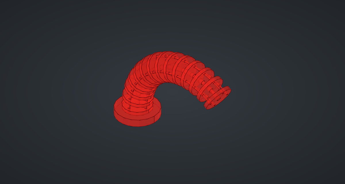
Turn Preview off on the construction steps.
What is happening
Every disk is the same vertebra, turned about the centre of curvature by its share of the bend, so the disk centres lie on an arc of length Length and radius Length/θ. A tendon at angle α round the disk lies on a parallel arc whose radius is smaller by r·cos α, so its length is θ·(Length/θ − r cos α) = Length − θ·r·cos α. That is the Panel’s formula. With the defaults, 120° of bend and 4.5 mm eyelets, the inside tendon is pulled in by 9.4 mm and the outside one let out by the same amount. The geometry tests measure the tendon curves and compare them with the formula.
Routing twist turns each disk’s eyelets further round, so the tendons spiral along the spine. The Panel’s formula is for straight tendons and no longer applies then. The robot updates in about a third of a second.
Things to try
-
Set Bend to 270 to curl the robot into a hook.
-
Set Routing twist to 15 for helically routed tendons.
-
Set Tendons to 3 and Disks to 30 for a finer spine.
-
Set Bend to 1: the robot stands straight and the Panel shows almost no change.