A turbine impeller in a cut-away shroud, with the number that matters most to its designer, the gap between blade tips and shroud, computed live as a tolerance stack-up. Twisted blades are lofted through three turned radial lines and arrayed round a hub; three Dimension components feed Stack-up and Monte Carlo Stack-up.
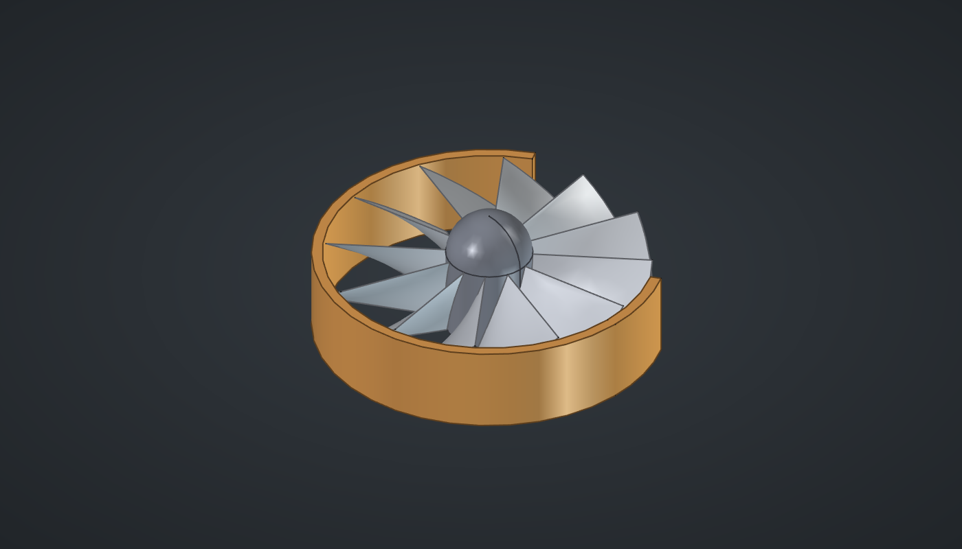
Reference: choose on the canvas toolbar to load the finished definition. The stack-up tutorial explains the tolerance components.
Build it
One blade
-
Place six sliders: Blades: 12 (3 – 24) with Decimals
0, Hub radius: 8 (4 – 15), Tip radius: 30 (15 – 50), Height: 16 (6 – 30), Twist: 40 (0 – 90), and Nominal clearance: 0.6 (0.1 – 2) with Decimals2. -
Place two Construct Point (Vector) components at (Hub radius, 0, 0) and (Tip radius, 0, 0), and a Line (Curve) between them: the blade’s root-to-tip line.
-
Place two Range (Maths) components with N
2: Section heights from 0 to Height, and Section turns from 0 to Twist. Each gives three values. -
Place a Move (Transform) with the Line → G and Section heights → Z, then a Rotate (Transform) with Section turns → A: three lines, each higher and turned further.
-
Place a Loft (Surface), Blade, with the three lines → C: a twisted blade.
The rotor
-
Place an Expression (Maths),
360/x, with Blades → x, and a Series (Sets) with it as N and Blades → C: the blade angles. -
Place a Rotate, Rotor, with Blade → G and the angles → A, with Graft on A: one blade per angle.
-
Place a Cylinder (Surface), Hub (Hub radius, Height), and a Sphere (Surface) of Hub radius moved up by Height: the nose.
The shroud
-
Place an Addition (Maths), Tip radius + Nominal clearance: the shroud’s bore radius. Add
2for the outer radius. -
Place two Cylinder components, outer (outer radius, Height) and inner (bore radius, L
40, moved down by10), and a Solid Difference (Intersect): the shroud ring. -
For the cut-away, place a Center Box (X, Y
80, Z60), a Move (X, Y40, Z-10) and a Rotate with A30, and subtract it from the ring with a second Solid Difference. The 30° keeps the cut off the cylinders' seams, which lie on the +X axis: a cut exactly through a seam is the case where FreeCAD’s Booleans are least reliable.
Tip clearance
-
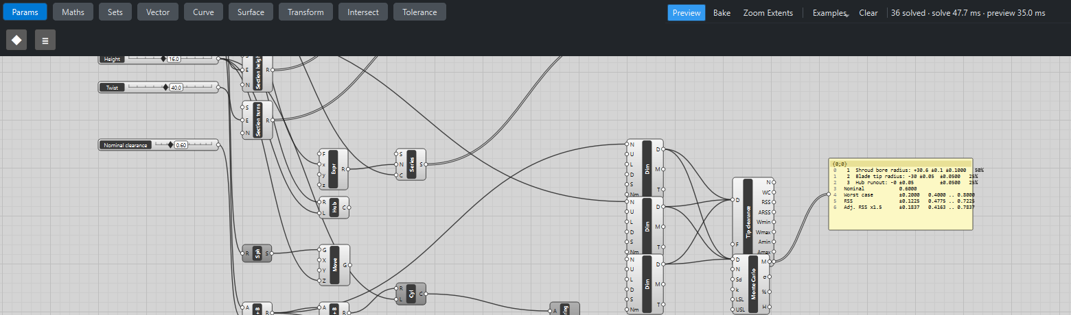
Place three Dimension (Tolerance) components:
-
Shroud bore radius: N from the bore Addition, ±0.1, direction +1.
-
Blade tip radius: N from Tip radius, ±0.05, direction −1.
-
Hub runout: N 0, ±0.05, direction −1.
-
-
Place a Stack-up (Tolerance) and wire all three dimensions into its D (hold Shift for the second and third): the chain bore − tip − runout. Wire its R (report) into a Panel (Params).
-
Place a Monte Carlo Stack-up (Tolerance) with the same three dimensions and set LSL to
0.3: the minimum acceptable clearance.
What is happening
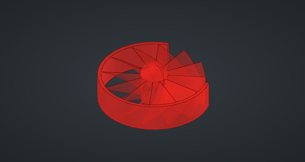
The blade is a smooth loft through three straight lines turned 0°, 20° and 40°: its leading edge leans round as it rises, like a real compressor blade (without the airfoil thickness). Grafting the rotation angles copies the one blade round the hub.
The clearance chain reads like a sentence: the shroud bore, minus the blade tip, minus however far the hub is off-centre. With the defaults the nominal clearance is 0.6 and the worst case ±0.2, so it never drops below 0.4: the Monte Carlo finds no build under the 0.3 limit. Lower Nominal clearance to 0.4 and the worst case reaches 0.2, and about half a percent of random builds fall below 0.3; at 0.3 about half of them do. The geometry tests check the nominal value and the worst-case tolerance.
The rotor updates in under half a second.
Things to try
-
Drag Nominal clearance down from 0.6 and watch the Panel and the Monte Carlo’s % output.
-
Set Twist to 0 for flat, fan-like blades, or to 90 for a strongly swept rotor.
-
Set Blades to 6 for an open propeller.
-
Tighten the shroud bore’s tolerance to ±0.05 and see how far the clearance can then be reduced.