Pin location
Opto-mechanical and precision modules are located by two dowel pins: a laser on an optical bench, a sensor head on a frame, a lens barrel in a housing. Whether the parts assemble, and how far the located part can shift and turn, follow from the pins, the holes and their spacings. Analysis › Pin Location (also on the PMI tab) works it out from the part’s PMI, worst case, with the method of Drake’s Dimensioning and Tolerancing Handbook, ch. 24.
Using it
Give the pins and the holes their PMI dimensions (PMI), with ISO 286 classes or deviations: a diameter on each pin and on each hole, or a diameter on the hole and a width on the slot. Select the four PMI dimensions and click Pin Location. Each pin is paired with the nearest hole; the round hole comes first, a slot second.
| Field | Meaning |
|---|---|
Hole spacing ±, Pin spacing ± |
Tolerances on the distances between the holes and between the pins. The distances themselves are measured between the axes in the model. |
Slot length |
Along the line of centres; it must take up the spacing tolerances (and the thermal growth). |
Distance to target, Pointing limit ± |
For a located optical axis: where it must hit, and how closely. |
Temperature difference |
Assembly temperature minus the reference temperature. |
Expansion |
Of the part with the holes and of the part with the pins, read from their materials when the analysis is made. |
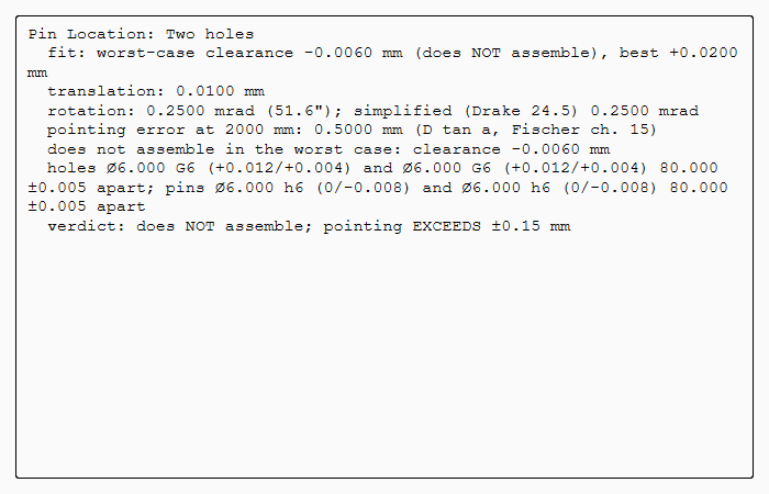
The result is a feature in the Part Navigator: Clearance, Translation, Rotation (mrad), Pointing (mm), the Verdict and the Report. It recomputes when the PMI (a class, a deviation) or the model (a spacing) changes. Double-click it to change the fields.
The method
Two holes. The parts assemble when the holes' clearances absorb the difference between the pin spacing dp and the hole spacing dh (Drake 24.2):
c = ½ (Øh1 + Øh2 − Øp1 − Øp2) − |dh − dp| ≥ 0
The located part turns by the angle of the triangle with sides dh, dp and e = ½(Øh1 − Øp1 + Øh2 − Øp2) (24.4); about (Øh − Øp)/dp (24.5). Translation is half the tighter pin’s clearance.
A hole and a slot. The slot runs along the line of centres, so the spacings leave the fit; only the slot’s length has to take them up (24.12). Translation is the hole’s half-clearance; the rotation follows from the pin line with one end in the hole’s clearance circle and the other in the slot’s clearance band: sin α = (Δhole + Δslot)/dp.
Temperature. Parts of different materials assembled ΔT away from the reference temperature change their spacings by dp ΔT |α1 − α2| (24.10). With two holes each hole must grow by that much, which adds half of it to the translation and ΔT |α1 − α2| to the rotation; a slot takes it up in its length.
Pointing. An angle error α moves a point D away by D tan α (Fischer, Mechanical Tolerance Stackup and Analysis, ch. 15): 0.1 mrad is 0.2 mm on a target 2 m away.
nxstyle/alignment.py holds the method; its unit tests cover each formula.
Drake calls 24.5 slightly conservative; with equal spacings 24.4 equals 2 asin(e/2d), which is larger than e/d by about (e/d)³/24, far below any tolerance. The report gives both.
Tutorial X takes a laser module from two holes that do not assemble to a hole and a slot, a wider pin base and finer classes, and checks it 10 K warm.