Tolerance analysis
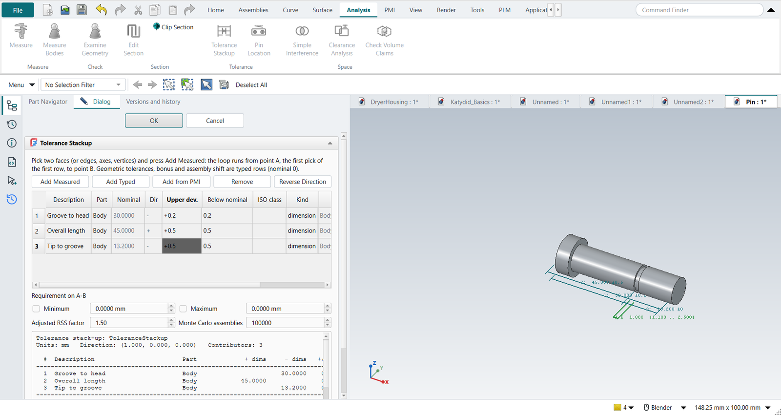
Analysis › Tolerance Stackup (also on the PMI tab) adds a stack-up to the part.
It is a document object, like a feature: it recomputes with the model, it is saved in the .FCStd, and its results are properties other features and expressions can read.
FreeCAD has no stack-up tool; NX’s is the separately licensed Tolerance Stackup Validation.
The method
The stack-up follows Bryan R. Fischer, Mechanical Tolerance Stackup and Analysis (2nd ed.):
-
The loop runs from point A to point B along one direction. Each dimension is a contributor in the stack direction (+) or against it (−); the result is the sum.
-
Every contributor is converted to equal-bilateral form first: 8.50 +0.25/−0.10 becomes 8.575 ±0.175. The report shows the conversion.
-
Geometrical tolerances, bonus and assembly shift are contributors with a nominal of 0 (Fischer’s rules): a zone T enters as ±T/2; the bonus of a feature at MMC as ±(LMC − MMC)/2 on its own line; a part floating on a fastener as ±(hole at LMC − fastener at MMC)/2, once for each part that floats.
| Method | Result |
|---|---|
Worst case |
±Σ ti |
RSS |
±√(Σ ti²), each tolerance taken as ±3σ |
Adjusted RSS |
factor × RSS, Fischer’s 1.5 by default (Adjusted RSS factor) |
MRSS |
Cf × RSS with Drake’s calculated factor Cf = 0.5 (Twc − Trss) / (Trss (√n − 1)) + 1 |
Monte Carlo |
each contributor drawn from a normal distribution (σ = t/3), or uniform; 100 000 assemblies by default, seeded so a run repeats |
With a requirement (Minimum, Maximum) each method gets a verdict, and the statistical prediction gives the share out of the requirement in ppm, Cp and Cpk. With fewer than four contributors the report recommends the worst-case result, as Fischer and Drake do.
Contributors
| Button | Adds |
|---|---|
Add Measured |
Two picked faces, edges, cylinder axes or vertices. The nominal and the direction come from the geometry, and follow every design change. The first pick of the first row is point A; the stack direction is the outward normal of that face (it points across the gap A bounds), Reverse Direction turns it round. |
Add Typed |
A row you type: a geometrical tolerance, a bonus, an assembly shift, or a dimension of a part that is not modelled. |
Add from PMI |
Selected PMI. A distance between two faces is measured and keeps the PMI’s tolerance; a size takes its ISO 286 class or the part’s ISO 2768 general tolerance; a feature control frame gives ±zone/2, plus a bonus row at MMC. |
In the table, Upper dev. is the upper deviation and Below nominal how far the lower limit lies below the nominal: a 16 g6 shaft (15.983 to 15.994) is 16, −0.006, 0.017.
Typing an ISO class such as g6 fills both from ISO 286.
In the model
The graphics window shows the loop as dimension lines stepped out beside the parts, numbered as in the table, and the result A–B in green or, when a verdict fails, in red.
The stack-up’s results are properties: Nominal, WorstCaseMin, WorstCaseMax, RSSMin, RSSMax, AdjustedMin, AdjustedMax, MonteCarloPPM, Verdict, and the full Report.
Double-click the stack-up in the Part Navigator to edit it.
A release package includes every stack-up as a report and a CSV table.
If a contributor cannot be resolved at a recompute, the stack-up gives no result at all rather than a wrong one. This happens when a measured row’s face is gone or its picks are missing, when a row’s PMI was deleted or is invalid, or when its fit class is unknown.
Valid turns false, the results are cleared, and Verdict says INVALID, not computed and which row broke.
Earlier versions left such a row out of the sum, or kept its last values, and reported a plausible result; a release package now refuses an invalid stack-up.
Fits
A fit is a stack-up of two contributors: the bore from its PMI, the shaft by its ISO 286 class, against the stack direction. Tutorial T does this for Ø16 H7/g6 and gets ISO 286’s clearance, 0.006 to 0.035 mm.
Checked against the books
The unit tests (tests/test_stackup.py) reproduce Fischer’s Example 7.1 and 8.1 (the pin of tutorial S: 0.6 to 3.0 worst case, RSS ±0.74, adjusted ±1.1), the 13-line ground plate assembly of his figure 14.11 (worst case −0.13, RSS ±1.0721, adjusted ±1.6082), Drake’s MRSS factor (1.3252 for his example) and Cogorno’s floating and fixed fastener, virtual and resultant condition formulas.